Resistance and Ohms Law
For many materials, the relationship between the current flowing through the material and the voltage across it is linear.
We call these resistive materials and the circuit elements we make from them resistors.
Ohms Law
The behavior of these resistors is modeled by Ohm’s Law.
V = IR
We can see that higher resistances require higher voltages to reach the same current.
I = V/R
If we solve this equation for the current, I, we can see that for the same voltage, higher resistances cause the current to decrease.
Visualization
The relationship between current and voltage for the resistor is a straight line with a slope equal to the resistance (in ohms or volts per ampere).
Ohm’s Law
Note that if you draw a straight horizontal line to represent an ideal voltage source, the intersection of that line and a resistor line will intersect at the value given by ohms law.
For example the 2 ohm resistor line meets the 10 volt horizontal line at 5 amps on the x-axis.
We can also see the linear relationship between current and voltage.
Power Dissipation
Resistors convert electrical energy into heat when the electrons collide with the material in the resistor. Examples of this include electric cooking elements and space heater elements.
Note that the power dissipated by the resistor is the area rectangle between a point on the line and the origin.
This lets us see that doubling the current or voltage dissipates four times as much power.
Wire resistance
We can calculate the resistance of a conductive object if we know its dimensions and properties.
R = resistivity \cdot \frac{length}{area} R = \rho \frac{l}{A}
- The resistance of a wire is proportional to
- the resistivity of the material
- the length of the wire
- It is inversely proportional to
- the cross-sectional area
Wire resistance
Electrical energy converted to heat in a wire is usually considered wasted energy.
This energy loss is seen as a reduced voltage across the load or device.
- Resistivity - property of the material - intensive
- Resistance - property of the wire - extensive
Units
- To get proper units of resistance in ohms
- Resistivity is expressed in Ohm/meter
- Length in meters
- Area in square meters
Energy Dissipation in a Resistor
As current flows through a resistor, the potential energy of the charges is converted to heat.
The power converted to heat in the resistor is the voltage across the resistor multiplied by the current through the resistor.
P = IV
The voltage and current through the resistor is related by Ohm’s Law V=IR. So, I can substitute the voltage in the equation and get
P = I (IR) P = I^2R
The power is proportional to the square of the current. This squared relationship is important for many circuit designs. When the current is in amps and the resistance is in ohms, the power is in watts.
We can do the same thing but use Ohm’s Law to substitute for the current and we get
P = \frac{V^2}{R}
Note that the power is not linear with the current or voltage but has a squared relationship.
Similarities to Thermal Conduction
The electrical resistance of a block of material is given by
\textrm{resistance} = \frac{\textrm{resistivity of material}\cdot\textrm{length of material}}{\textrm{cross sectional area of material}}
R = \frac{\rho \cdot l}{A}
The UA of a block of material has the formula
\textrm{UA value} = \frac{\textrm{thermal conductivity of material} \cdot \textrm{cross sectional area}}{\textrm{thickness of material}}
UA = \frac{k \cdot A}{t}
These are basically reciprocals of each other.
Ideal elements
Circuits are an idealized representation of a real electrical system that aids analysis.
Simplifying assumptions include:
- use of ideal elements in place of physical elements
- ideal wires with zero resistance
Idealized circuit representation
- Lines have no resistance and uniform voltage
- Real elements (heaters, filaments, batteries) are represented as ideal models
IV Curve
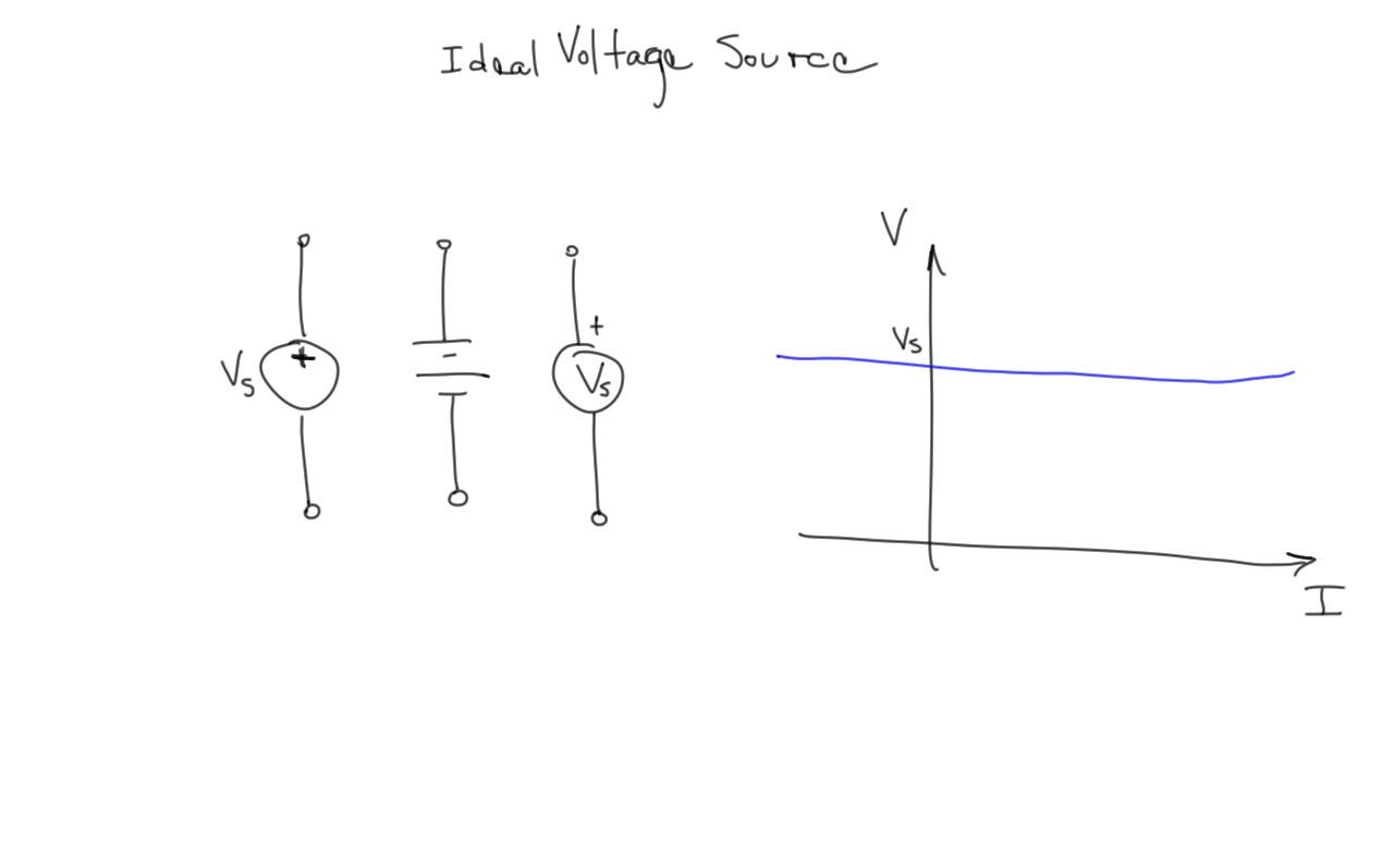
IV curves show the voltage value for a given current.
Ideal Voltage Source
- An ideal voltage source can deliver any amount of current while holding its voltage constant.
Ideal Resistor
An ideal resistor obeys Ohm’s Law, V=IR 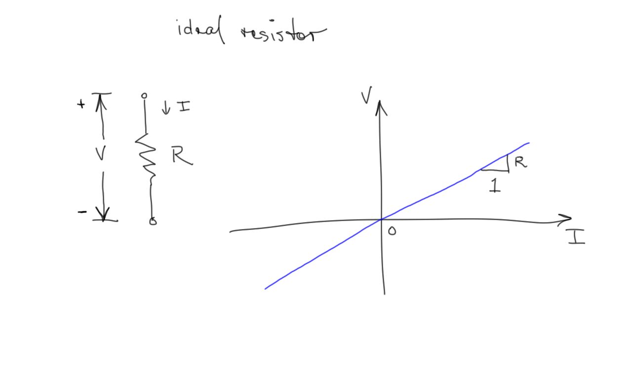
Ohm’s Law
V = IR The current in a resistor is proportional to the voltage across it. The constant of proportionality is the resistance.
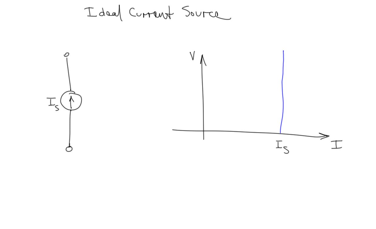
Ideal Current Source
- An ideal current source delivers a fixed amount of current no matter the voltage at its terminals
Kirchhoff’s Current Law
- The sum of currents flowing into a node must equal the sum of the currents leaving the node at any instant.
- Water flow or automobile traffic provide some intuition.
Kirchhoff’s Voltage Law
- The sum of the voltages around any loop of a circuit at any instant is zero.
- Hiking a trail provides some intuition.
Equivalent resistances
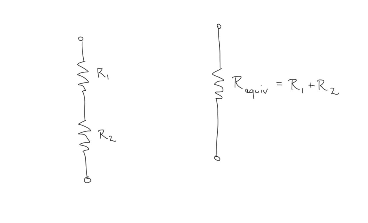
- We can use Ohm’s Law and Kirchoff’s Laws to determine an equivalent resistance to model a network of resistors.
Resistors in series
- Resistors in series have the same current flowing through each one
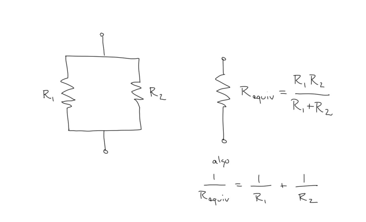
Resistors in parallel
- Resistors in parallel have the same voltage across their terminals
